Introduction to Colloid Mills
In the world of industrial processing, where creating perfectly blended, stable, and uniform products is paramount, the colloid mill stands as a technological cornerstone. This sophisticated yet elegantly simple machine is the silent workhorse behind countless products we use daily. From the smooth texture of your favorite mayonnaise and the consistent potency of pharmaceutical creams to the vibrant hues of industrial paints and the luxurious feel of cosmetic lotions, colloid mills play a crucial role.
The Fundamental Principle of a Colloid Mill
The core principle of a colloid mill is high-shear fluid mechanical force , often referred to as shear hydraulics .
The Science of Shear and Impact
The colloid mill operates on a simple yet effective mechanism:
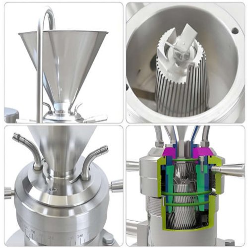
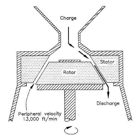
- Rotor-Stator Design: The heart of the mill consists of a high-speed rotor and a stationary stator, separated by an extremely narrow, adjustable clearance (from 0.001 to 0.125 inches).
- Shear Force Generation: As the liquid mixture is fed into the gap, the rapid rotation of the rotor creates intense tangential shear and turbulence.
- Particle Size Reduction: The combined action of shear, hydraulic shear, cavitation, and centrifugal force tears apart agglomerates and reduces droplet/particle size.
- Dispersion & Homogenization: This mechanical action ensures a uniform, stable, and homogenized colloidal dispersion or emulsion.
In essence, the colloid mill transforms coarse mixtures into micro-fine dispersions through mechanical tearing, rather than conventional grinding.
Detailed Construction of a Colloid Mill
Understanding the construction of a colloid mill is key to appreciating its efficiency. While designs may vary, the main components remain consistent.
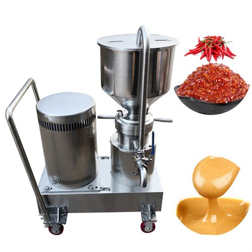
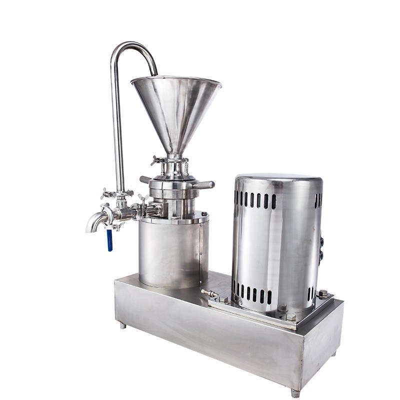
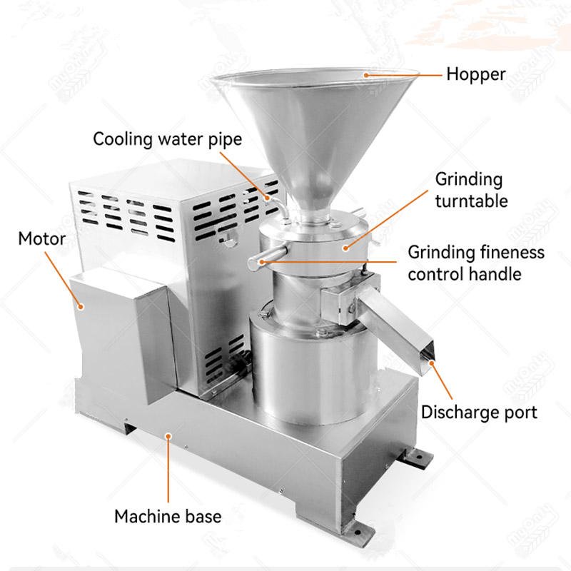
- Feed Hopper / Inlet Funnel:
- Function: This is the entry point for the raw material or pre-mix. It is designed to guide the product smoothly into the milling chamber, often featuring a wide opening for easy feeding, which may be gravity-fed or connected to a pump for continuous operation.
- Construction: Typically fabricated from stainless steel (Grade 304 or 316) for corrosion resistance and ease of cleaning. It may include a deflector to direct flow.
- Rotor (Impeller):
- Function: The central rotating element that is the primary source of kinetic energy. Mounted directly on the motor shaft or a connected spindle, its high-speed rotation (typically 3,000 to 20,000 RPM) generates the necessary centrifugal and shear forces.
- Construction: Made from highly wear-resistant materials like hardened stainless steel, stellite, or carbon steel. The surface can be smooth, corrugated, slotted, or toothed, depending on the required shear intensity and application.
- Stator (Housing):
- Function: The stationary element that forms the counterpart to the rotor. It houses the rotor and, together with it, defines the precise shear gap. The inner surface of the stator works in tandem with the rotor surface to create the shearing action.
- Construction: Also constructed from durable, corrosion-resistant materials. Its inner surface geometry often matches or complements the rotor design (e.g., a toothed rotor working against a slotted stator).
- Milling Chamber / Casing:
- Function: The enclosed body that contains the rotor-stator assembly and contains the product during processing. It withstands the internal pressures and forces generated during operation.
- Construction: Robust stainless steel construction. A critical feature is the jacketing that often surrounds the chamber. This allows for the circulation of cooling water or heating media (steam/thermic fluid) to control the product temperature, which is vital for heat-sensitive materials like pharmaceuticals and food.
- Gap Adjustment Mechanism:
- Function: This is one of the most crucial features. It allows for precise micrometer-level adjustment of the clearance between the rotor and stator. This adjustment directly controls the shear intensity and, consequently, the fineness of the end product.
- Construction: Usually consists of a manual handwheel, a graduated scale, and a precision screw mechanism that moves the stator axially. Advanced models may feature hydraulic or automated adjustment.
- Discharge Outlet:
- Function: The exit point for the processed, homogenized product. Its design ensures smooth outflow without causing back-pressure or re-agglomeration.
- Construction: A flanged or threaded stainless steel outlet, often positioned tangentially to the milling chamber.
- Drive Motor and Power Transmission:
- Function: Provides the mechanical power required to drive the rotor at high speeds. Variable Frequency Drives (VFDs) are commonly used to allow precise control over the rotor speed.
- Construction: An electric motor (often a high-speed induction motor) coupled directly or via a belt drive to the rotor shaft. The assembly is mounted on a sturdy base frame.
- Base Frame:
- Function: Provides a rigid and stable foundation for the entire assembly, minimizing vibration and ensuring safe operation.
- Construction: Made from heavy-duty steel or stainless steel, often with anti-vibration pads.
Main Components and Their Functions of a colloid mill
| COMPONENT | FUNCTION | MATERIAL (COMMON) |
|---|---|---|
| Hopper/Feed Inlet | Introduces the material into the grinding chamber. | Stainless Steel (SS 316/304) |
| Rotor | The high-speed rotating element that generates shear force. | Hardened Steel, Corrosion-resistant alloys |
| Stator | The fixed element that, with the rotor, defines the shear gap. | Hardened Steel, Corrosion-resistant alloys |
| Milling Chamber | Enclosed housing where the actual size reduction occurs. | Stainless Steel, often jacketed for temperature control |
| Adjustment Handle | Allows precise control of the gap between rotor and stator. | Steel |
| Discharge Outlet | Releases the processed, homogenized product. | Stainless Steel |
| Motor | Provides the mechanical power to drive the rotor at high speeds (3,600 – 20,000 RPM). | Electric, often with variable speed control |
| Base Frame | Provides structural support and stability to the entire assembly. | Sturdy Steel |
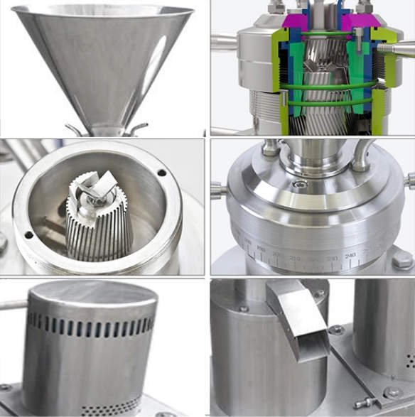
Design Variations
- Vertical vs. Horizontal: Vertical colloid mills are common for their compact footprint and easy cleaning. Horizontal colloid mills are often used for continuous, high-volume production.
- Contact Surface Design: The rotor and stator surfaces can be smooth, corrugated, or toothed to vary the shear intensity for different materials.
Working and Operational Process
The working of a colloid mill is a continuous, dynamic process. Here is a step-by-step breakdown of its operation:
Stage 1: Feeding and Introduction
The process begins with the introduction of the raw material. This is typically a coarse pre-mix or a two-phase liquid system (like oil and water). The material is fed into the mill via the feed hopper, either by gravity for batch processing or via a feed pump for continuous, high-volume production lines.
Stage 2: Centrifugal Acceleration and Pre-Mixing
As the material enters the central intake of the milling chamber, it is immediately acted upon by the high-speed rotor. The centrifugal force generated by the spinning rotor throws the material radially outward towards the periphery of the chamber and into the critical gap between the rotor and stator.
Stage 3: The High-Shear Milling Zone
This is the heart of the process of colloid mill. The material is violently forced through the microscopically small, adjustable gap between the rotor and stator. In this confined space, several actions occur simultaneously:
- The high velocity difference between the moving rotor surface and the stationary stator surface creates extreme laminar shear .
- The sudden constriction and release cause intense turbulence and hydraulic shear .
- Cavitation bubbles may form and collapse.
- If the surfaces are textured (toothed/corrugated), additional impact and attrition forces come into play. This multi-force environment effectively tears apart droplet clusters, breaks down solid agglomerates, and reduces particle size down to the colloidal range.
Stage 4: Discharge and Optional Recirculation
The finely processed dispersion exits the shear zone and is discharged through the outlet. For many applications, a single pass is sufficient. However, to achieve an ultra-fine, monomodal particle size distribution or absolute homogeneity, the product may be recirculated . This involves piping the discharged product back into the feed hopper for multiple passes through the shear zone. Each pass further refines the dispersion.
Stage 5: Temperature Control
Throughout the process, the jacketed milling chamber is actively used for temperature control. Cooling water is circulated to dissipate the heat generated by shear friction, which is essential for protecting heat-sensitive ingredients. Conversely, for viscous products like fats or waxes, steam or hot fluid may be used to maintain optimal processing viscosity.
Critical Advantages of Using a Colloid Mill
The widespread adoption of colloid mills is due to a compelling set of advantages:
- Superior Particle Size Reduction: Capable of achieving consistent particle sizes in the crucial 1-20 micron range, ideal for stable colloids and emulsions.
- Excellent Product Stability: The intense shearing action creates emulsions and dispersions with very small droplet/particle sizes, which resist separation (creaming, sedimentation) for extended shelf life.
- High Efficiency and Versatility: Can handle a remarkably wide range of viscosities, from low-viscosity solutions to very thick pastes, and process diverse materials.
- Adjustable Fineness: The micrometer gap adjustment provides excellent control over the final product texture and fineness without needing to change parts.
- Robust and Durable Construction: Built with hardened surfaces and sturdy materials, it offers a long operational life with minimal maintenance.
- Ease of Operation and Cleaning: Designed with sanitary standards in mind (often compliant with cGMP, FDA, 3A), many models allow for quick disassembly and support Clean-in-Place (CIP) procedures.
Limitations and Considerations
While powerful, colloid mills have certain limitations that must be considered during process design:
Noise and Vibration: High-speed operation can generate significant noise and vibration, requiring proper installation and maintenance.
Heat Generation: The high shear process inherently generates heat, which can be detrimental to thermolabile products. Effective cooling via the jacket is mandatory in such cases.
Not for Dry Milling: Designed exclusively for wet grinding, dispersion, and emulsification. It cannot process dry powders.
Abrasive Wear: Processing highly abrasive slurries can lead to accelerated wear of the rotor and stator, increasing maintenance costs and potentially causing metallic contamination. Material selection (e.g., ceramic coatings) is key.
Clogging Potential: Products with very long fibrous content or extremely high, putty-like viscosity may pose feeding or clogging challenges.